The design of machines, equipment, mechatronic smart stuctures… represents a very complex problem. It deals with the synthesis of actual knowledge in various technical areas. In this chapter, possibilities of integration of the LDS theory results in this field will be outlined.
Machines, equipment and smart structures can be very often interpreted as real distributed parameter control systems. Here, information and control processes take place. For efficient operation of such objects, it is useful to ensure both, minimal complexity of information processes involved and optimal dynamics of control processes.
Transformations in particular blocks of distributed parameter control systems are given by dynamic properties of the system being controlled in both, space and time domains. These have close connection with spatial and construction layout of the object.
Appropriate choice of components and spatial layout of machines and equipment being designed offers possibilities to optimize the performance of distributed parameter control systems. The main goal here is to achieve optimal operation of the designed system: optimal control processes with minimal conplexity of information processes. It is an optimal distributed parameter system from the point of view of cybernetics.
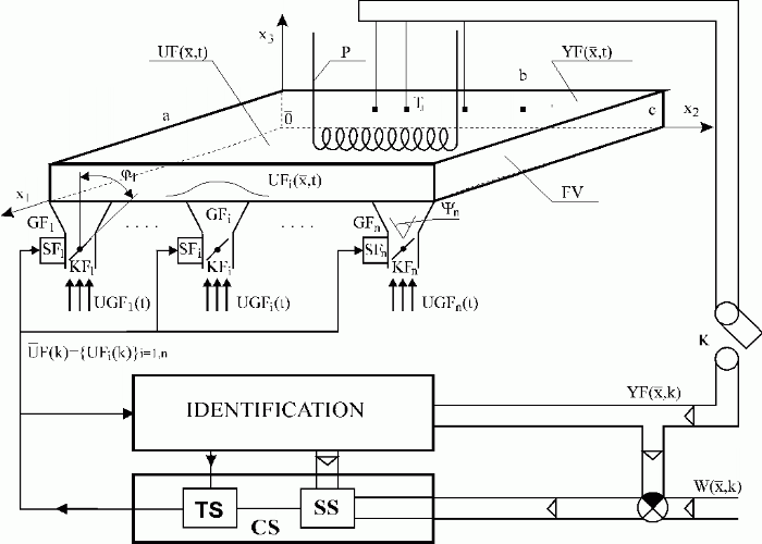
Due to the complexity of problems described above, it is not possible to offer any complete guides to the design problems of optimal machines and equipment as distributed parameter systems. Therefore, in this chapter, only some basic types of problems connected with construction optimization will be picked up. As a pattern problem let us analyse optimization of the fluidized bed fireplace construction layout – see Fig. 8.1.
Steam generator with fluidized bed fireplace (FV) is operating under varying operating conditions. Transition from one operating mode to another may cause considerable changes in temperature field. The main goal of the control is to maintain, under particular operating conditions, the temperature of FV in the neighbourhood of optimal desulphurisation temperature as well as to smooth the temperature fields between the operating modes such that the fuel consumption is minimal.
In general, in some neighbourhood of the steady-state, the following relationship has to be fulfilled :
 |
(8.1) |
where ![]() is the FV optimal desulphurisation temperature,
is the FV optimal desulphurisation temperature, ![]() – FV steady-state reduced transient responses,
– FV steady-state reduced transient responses, ![]() – coordinate of the i-th fuel and additives input,
– coordinate of the i-th fuel and additives input, ![]() – controlled variables in the time domain,
– controlled variables in the time domain,  – control quality,
 ![]() – norm appropriately chosen.
– norm appropriately chosen.
FV dynamic responses in the steady-state depend upon construction parameters and space layout of the fireplace; i.e. fireplace dimensions, location of particular pneumatic transport subsystems, size of the angles,  i}i
i}i
The main scope of design when optimizing the fireplace’s layout is to be focused on finding parameters leading to control performance prescribed, provided that minimal number of pneumatic transport subsystems are involved. Further, there are to be found such components and technical solutions of particular construction nodes, which ensures, together with optimal control loops, to fulfill the control objective, eq. (8.1).

Fig. 8.1 Real distributed parameter control system
| FV | – fluidized bed |
| P | – high pressure part of the steam generator |
| a,b,c | – geometrical dimensions of the fireplace |
| – x1, x2, x3 | |
| {Tj}j | – thermometers |
| {GFi}i=1,n | – subsystems of pneumatic fuel and additive transport, generators of distributed input variables |
{ i}i=1,n
 |
– output angles of pneumatic fuel and additive transport subsystems |
| {SFi}i=1,n | – servodrives |
| {KFi}i=1,n | – control valves of pneumatic fuel and additive transport system |
{ i}i=1,n i}i=1,n |
– angular displacement of valves,{KFi}i=1,n |
| – optimal desulphurisation temperature | |
| – thermal field of FV, distributed output variable | |
| – total FV distributed input variable | |
| – FV distributed input variables | |
| – fuel and additive flows, lumped input variables for {GFi}i=1,n | |
| {UFi(k)}i=1,n | – vector of lumped input variables |
| K | – sampling |
| TS/SS | – time/space synthesis |
| CS | – control synthesis |
The desired control performance in time domain is to be achieved by feedback loops in the TS block. The control system dynamics is given by dynamic behaviours of servodrives as well as pneumatic transport subsystems and FV.
The process of desulphurisation goes on only in the close neighbourhood of the optimal desulphurising temperature. Therefore, it is necessary to design the number and location of temperature measurement points very thoroughly. The attention of the designer has to be, therefore, focused also on design of FV temperature measurement system involving a minimal number of measuring points. In such a way, the complexity of information processes involved in control system can be minimized and effective desulphurisation can be achieved.
A similar way of analysis can be proposed also for distributed systems of hyperbolic types. Such systems are e.g. oscillating mechatronic systems of continuum mechanics where measurement, generation of distributed input and control are carried out on the basis of smart material structures. One of the essential tasks in design of such systems is also the sensor location problem and minimization of the number of lumped control inputs, see Figs. 9.1.3.1 and 9.1.7.1.
As to formulation and solution of problems defined above in the time domain , well established methods from the field of lumped control system design are at the disposal. Therefore, in demonstration chapters, hereinafter, formulation and solution of optimization problems in the space domain will be mainly emphasized. In particular, the following topics will be discussed:
– minimization of number of measuring points
– minimization of number of control variables.
| <<< Previous | Next >>> |