This section provides the description of some distributed parameter control problems. These examples can be also viewed through DPS Examples block.

Control of the temperature field in the volume of complex shape metal body
Complex shape metal body is being heated through contact heating elements on subdomains Ω1 – Ω4. Distributed transient characteristics (transient responses) are numerically calculated in COMSOL software. The dynamics of control inputs comprises of actuating member transfer functions SA(s), input generator transfer functions SG(s) and shaping units T. The control task is to bring the temperature field to a new steady state by means of PID control synthesis.

Legend
Ω – definition domain of the heated body
Ωi – i-th subdomain of the heating element (i-th boundary condition region)
SAi – i-th transfer function of the actuating member (voltage source time-dynamics)
SGi – i-th transfer function of the distributed input generator (heating element time-dynamics)
Ui – i-th lumped input quantity (i-th control input, voltage)
Ti – i-th shaping unit (heat flux distribution over subdomain region)
HLDS – lumped input / distributed output system (voltage / temperature field)
K – sampling (Simulink inherited)
Model data
Material – steel (98.5 Fe, 1.3C, 0.1Si, 0.1Mn)
Number of lumped inputs – 4, individually controlled
Ti (x, y, z), i = 1,2 and 4 – conical shape
Ti (x, y, z), i = 3 – pyramidal shape
SAi , i = 1,2,3 and 4 – const = 1 (neglected time-dynamics, immediate reactions)
SGi , i = 1,2,3 and 4 – const = 1 (neglected time-dynamics, immediate reactions)
Distributed transient characteristics (system dynamics identification)
U1 – control voltage step change / temperature field transient response


U2 – control voltage step change / temperature field transient response


U3 – control voltage step change / temperature field transient response


U4 – control voltage step change / temperature field transient response


Control process (reaching a new steady-state temperature field)


Oscillation control of the „smart“ structure beam
Complex shape metal beam is being deflected using piezoceramic actuators attached to subdomains Ω1 – Ω3. Distributed transient characteristics (transient responses) are numerically calculated in ANSYS software. The dynamics of control inputs comprises of actuating member transfer functions SA(s), input generator transfer functions SG(s) and shaping units T. The control task is to bring the beam into a new steady state shape by means of PID control synthesis.

Legend
Ω – definition domain of the metal beam
Ωi – i-th subdomain of the piezo element (i-th boundary condition region)
SAi – i-th transfer function of the actuating member (voltage source time-dynamics)
SGi – i-th transfer function of the distributed input generator (piezo element time-dynamics)
Ui – i-th lumped input quantity (i-th control input, voltage)
Ti – i-th shaping unit (load distribution over subdomain region)
HLDS – lumped input / distributed output system (voltage / displacement)
K – sampling (Simulink inherited)
Model data
Material – aluminium alloy
Number of lumped inputs – 3, individually controlled
Ti (x, y, z), i = 1,2 and 3 – conical shape
SAi , i = 1,2,3 – const = 1 (neglected time-dynamics, immediate reactions)
SGi , i = 1,2,3 – const = 1 (neglected time-dynamics, immediate reactions)
Distributed transient characteristics (system dynamics identification)
U1 – control voltage step change / displacement transient response

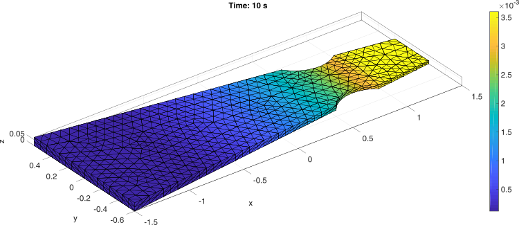
U2 – control voltage step change / displacement transient response


U3 – control voltage step change / displacement transient response


Control process (reaching a new steady-state displacement field)


Control of the temperature field in the glass melting furnace
Glass melting furnace is being heated by gas burners represented by triangular submains Ω1 – Ω4. Distributed transient characteristics (transient responses) are numerically calculated in Matlab PDE Toolbox. The control task is to reject disturbances caused by changing operating conditions in the gas furnace by means of adaptive control synthesis.
Furnace diagram

Legend
Y(x, y, t) – Temperature field of the glass furnace arch
Ui (t) – i-th lumped input quantity (i-th control input, servo unit control signal)
T1-11 – temperature sensors (thermocouples)
Model data

a = 0.00491 (m2 s-1), b = 0.00026 (m s-1), c = 1418 (J kg-1 K-1), rho = 2741 (kg m-3)
Number of lumped inputs – 4, individually controlled
Ti (x, y), i = 1,2,3 and 4 – pyramidal shape
SAi , i = 1,2,3 and 4 – const = 1 (neglected time-dynamics, immediate reactions)
SGi , i = 1,2,3 and 4 – const = 1 (neglected time-dynamics, immediate reactions)
Distributed transient characteristics (system dynamics identification)
U1 – gas flow step change / temperature transient response


U2 – gas flow step change / temperature transient response


U3 – gas flow step change / temperature transient response


U4 – gas flow step change / temperature transient response


Control process (reaching a new steady-state temperature field)


Groundwater remediation control
Groundwater remediation process is to be designed for a given area using 10 extraction wells (see dots on the map), arranged in two lines (HS, HO). Distributed transient characteristics (transient responses) are numerically calculated in Modflow software. The control task is to follow the desired shape of groundwater hydraulic-head over remediation area by means of extraction wells.
Map of groundwater remediation area

Legend
solid lines – groundwater hydraulic-head iso-lines (m)
hydraulic head – height of the groundwater surface relative to the sea level (m)
HS – first line of extraction wells (dots)
HO – second line of extraction wells (dots)
Distributed transient characteristics (system dynamics
U1 – extraction rate step change / hydraulic-head transient response